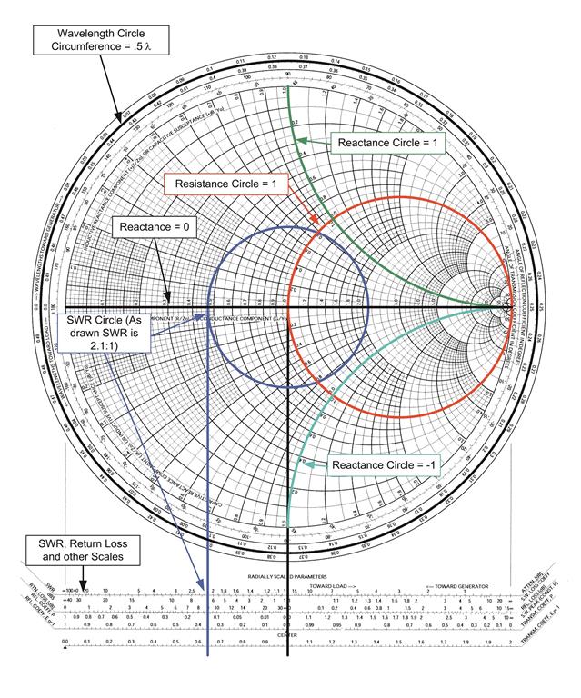
smith chart and the Input Impedance Characteristic of the simulated results shows the input.

The lecturers all have an academic and industrial background and are embedded in the Center for Wireless Technology Eindhoven (CWT/e) of Eindhoven University of Technology, The Netherlands. The Smith chart is commonly used to impedance match RF devices, such as amplifiers, antennas and transceiver devices. impedance matching between the antenna and the chip is very. with rectangular graphs, Smith Charts, polar grids, and antenna plots.
Antenna smith chart full#
After finalizing the course a certificate can be obtained (5 ECTS), which can be used when you start a full MSc program at Eindhoven University of Technology. Smith (19051987) and independently by Mizuhashi Tosaku, is a graphical calculator or nomogram designed for. The data cursor for the Smith Chart can display trace information as impedance. The course is supported by a book written by the team of lecturers, which will be made available to the students. Throughout the course you will work on the design challenge in which you will design a complete active phased array system, including antennas, beamformers and amplifiers.
Antenna smith chart how to#
Next to this, we will provide you hands-on experience in a design-challenge in which you will learn how to design microwave circuits and antennas. The web lectures are supported by many on-line quizzes in which you can practice the background theory. We will provide you with the required theoretical foundation as well as hands-on experience using state-of-the-art design tools.

Future applications, like millimeter-wave 5G/beyond-5G wireless communications or automotive radar, require experts that can co-design highly integrated antenna systems that include both antennas and microwave electronics. That is, we want to minimize the reflection coefficient, to reduce the power reflected from the load (the antenna), and maximize the power delivered to the antenna. Introduction to Impedance Matching Impedance Matching is the process of removing mismatch loss. The Smith chart is convenient for antennas and. The Smith Chart makes this easy to visualize. The course combines both passive and active microwave circuits as well as antenna systems. report presents measurements of the VSWR, related to antennas, by means of a. We divide the resistance and capacitive reactance of the antenna by 50 and. Corresponding to loop on smith chart, plot on VSWR is less than 2 ,which is bandwidth of the antenna which has appeared only due to coupling and is absent. This unique Master-level course provides you with in-depth know-how of microwave engineering and antennas. Basically, a Smith chart is a polar graph of normalized line impedance in the.


 0 kommentar(er)
